Network Paths: Routing, NAT, and State
- Part I — Diagnosing the local Proxy ARP case
- Part II — From one local hop to the whole Internet
- Part III — Symmetric protocols, asymmetric initiation
- Final summary: the communication path is also state
A Linux client produced a surprising set of network observations:
- two destination addresses were covered by the client’s directly connected route;
- all observed IPv4 neighbors resolved to one MAC address;
traceroutenevertheless reported the default gateway before a destination in the same configured subnet.
On a conventional Ethernet LAN, an on-link destination answers ARP with its own MAC and is reached without an IP router. Why does this network behave differently?
This case study works from the evidence outward. It uses the observations to connect subnet masks, Layer 2, Layer 3, ARP, Proxy ARP, routing, and traceroute, then extends the same principles to Internet communication through a NAT gateway. The addresses and interface names below are fictional, but their network relationships match the original observation.
The discussion has three parts:
- diagnose the surprising local Proxy ARP and traceroute results;
- follow a packet from a private host through Layer 2, routers, NAT, and back;
- locate state in IP, UDP, TCP, NAT, and applications, then explain the practical asymmetry between an initiator and a responder.
Part I — Diagnosing the local Proxy ARP case
We begin with the commands exactly as the client sees them, then explain the apparent contradiction one layer at a time.
The observations
The client first sent ARP probes to 192.168.24.65:
user@client-host:~$ sudo arping -c 3 -I wlan0 192.168.24.65
ARPING 192.168.24.65
58 bytes from 02:00:00:00:00:01 (192.168.24.65): index=0 time=34.995 msec
58 bytes from 02:00:00:00:00:01 (192.168.24.65): index=1 time=38.442 msec
58 bytes from 02:00:00:00:00:01 (192.168.24.65): index=2 time=37.416 msec

--- 192.168.24.65 statistics ---
3 packets transmitted, 3 packets received, 0% unanswered (0 extra)
rtt min/avg/max/std-dev = 34.995/36.951/38.442/1.445 ms
A trace to another address showed two IP hops:
user@client-host:~$ traceroute -n 192.168.16.75
traceroute to 192.168.16.75 (192.168.16.75), 30 hops max, 60 byte packets
 1  192.168.16.1   12.602 ms  12.495 ms  12.452 ms
 2  192.168.16.75   6.491 ms   8.998 ms   8.962 ms
The ARP cache contained the same MAC for the gateway and both peers:
user@client-host:~$ arp -a
? (192.168.24.65) at 02:00:00:00:00:01 [ether] on wlan0
_gateway (192.168.16.1) at 02:00:00:00:00:01 [ether] on wlan0
? (192.168.16.75) at 02:00:00:00:00:01 [ether] on wlan0
Finally, the routing table said that the entire /20 was directly connected:
user@client-host:~$ route -n
Kernel IP routing table
Destination      Gateway          Genmask          Flags Metric Ref Use Iface
0.0.0.0          192.168.16.1     0.0.0.0          UG    600    0   0   wlan0
192.168.16.0     0.0.0.0          255.255.240.0    U     600    0   0   wlan0
192.168.50.0     0.0.0.0          255.255.255.0    U     100    0   0   eth0
The eth0 network is unrelated to this investigation. The important entries are the directly connected /20 on wlan0 and the default route through 192.168.16.1.
First principle: a subnet is a Layer 3 decision
An IPv4 subnet mask divides an address into:
- a network prefix, used to identify the subnet;
- a host part, used to identify an interface within that subnet.
The route uses mask 255.255.240.0, which is /20 because its binary representation contains twenty leading 1 bits:
255       .255       .240      .0
11111111  .11111111  .11110000 .00000000
The third octet has four network bits and four host bits. Its subnet block size is:
256 - 240 = 16
The block containing third-octet value 16 therefore runs from 16 through 31:
| Property | Value |
|---|---|
| Network | 192.168.16.0/20 |
| Mask | 255.255.240.0 |
| Address range | 192.168.16.0–192.168.31.255 |
| Directed broadcast | 192.168.31.255 |
| Typical usable host range | 192.168.16.1–192.168.31.254 |
Both test destinations are inside that range:
192.168.16.75  AND 255.255.240.0 = 192.168.16.0
192.168.24.65  AND 255.255.240.0 = 192.168.16.0
The local kernel therefore classifies both as on-link. It does not select the default route for either one. Instead, it tries to resolve the destination IP address itself into a link-layer address.
This is an important distinction:
The subnet mask controls the host’s Layer 3 route selection. It does not guarantee that every address in the prefix is directly reachable through a normal shared Layer 2 LAN.
Layer 2 and Layer 3 answer different questions
In this case, the two most important layers are:
| Layer | Unit and address | Main question |
|---|---|---|
| Layer 2, data link | Ethernet/Wi-Fi frame and MAC address | Which neighbor receives this frame on the current link? |
| Layer 3, network | IP packet and IP address | Which interface or router moves this packet toward its destination? |
A switch or bridge normally forwards Layer 2 frames by destination MAC. A router accepts an IP packet on one interface, consults a Layer 3 routing table, decrements the packet’s TTL, and sends it onward in a new link-layer frame.
The IP source and destination generally remain end-to-end. The MAC addresses are only for the current link and can change at every routed hop.
What a conventional same-subnet LAN would do
Assume client A wants to reach 192.168.16.75. On a normal shared Layer 2 LAN:
- A’s
/20route says the destination is on-link. - A broadcasts: “Who has
192.168.16.75?” - The destination itself replies with its own MAC.
- A sends an Ethernet frame directly to that MAC.
- A switch may relay the frame, but no router processes the IP packet.
- Because no router forwards it, the packet’s TTL is not decremented.
The destination would normally be the first and only result in traceroute.
The observed network differs in two ways: the supposed peers resolve to the gateway’s apparent MAC, and the gateway appears as an IP hop.
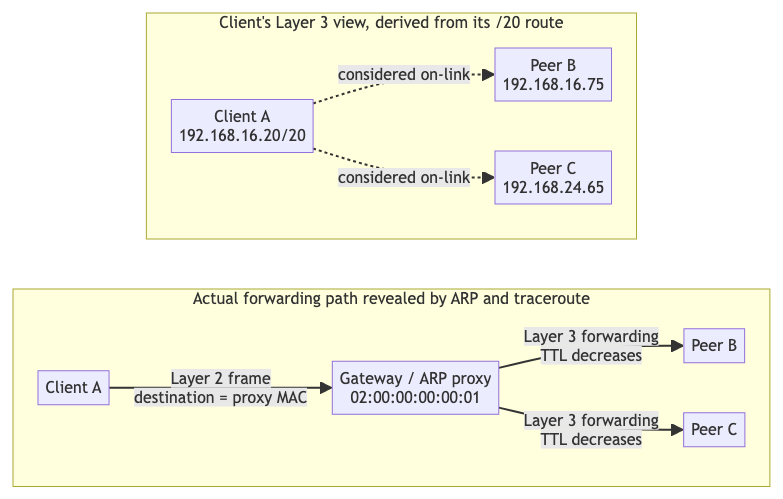
The important distinction is between the client’s logical view and the actual forwarding path.
From the client’s Layer 3 configuration, every address in 192.168.16.0/20 is on-link. The client therefore treats 192.168.16.75 and 192.168.24.65 as directly reachable IP neighbors: it issues ARP for each destination itself instead of sending the packet to the configured default gateway.
But ARP does not return each peer’s own MAC. It returns the proxy’s MAC. The client consequently sends a Layer 2 frame to the proxy, even though the IP packet inside that frame is addressed to the peer. The proxy then performs a Layer 3 forwarding operation, which is why TTL decreases and the gateway appears in traceroute.
It would be imprecise to say that the peers are “in the same subnet at Layer 2,” because a subnet and subnet mask are Layer 3 concepts. It is also not proven that every client occupies a physically separate network. A precise statement supported by the captures is:
The client considers the peers on-link because they share its configured Layer 3 prefix, but their frames are delivered to a proxy MAC and the enclosed IP packets are forwarded through a Layer 3 gateway.
ARP: turning the selected next hop into a MAC address
ARP, the Address Resolution Protocol, connects the Layer 3 routing decision to Layer 2 delivery.
For each IPv4 packet, the host first decides the next-hop IP:
- on-link destination: next hop is the destination IP;
- off-link destination: next hop is a router, usually the default gateway.
It then uses ARP to obtain a MAC address for that next hop.
An ARP request is carried in a Layer 2 broadcast frame. It asks which interface owns a particular IPv4 address. The reply normally comes from the owner and is usually unicast back to the requester. The resulting IP-to-MAC mapping is cached in the neighbor table.
ARP is often described as operating “between Layer 2 and Layer 3” because it carries an IP address question but exists to produce a link-layer address. It does not route application traffic and it does not decrement IP TTL.
Proxy ARP: answering on behalf of another address
With Proxy ARP, a router or other network element answers an ARP request for an address that is not assigned to the requesting-side interface. It effectively says:
“To reach that IP address, send the Ethernet frame to my MAC address.”
The sender still believes the IP destination is on-link. It builds a frame like this:
Ethernet source:      client's MAC
Ethernet destination: 02:00:00:00:00:01
IP source:            client's IP
IP destination:       192.168.24.65
Notice that the Ethernet destination identifies the immediate receiver, while the IP destination remains the final peer.
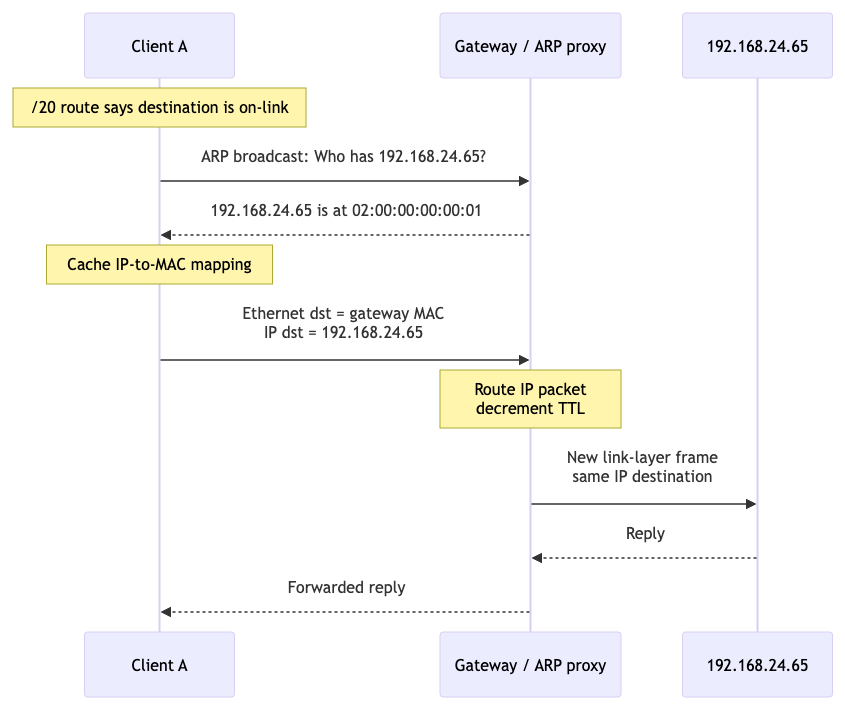
Proxy ARP only supplies the MAC mapping. After receiving the frame, the gateway must separately perform IP forwarding:
- remove the incoming link-layer framing;
- inspect the IP destination;
- consult its routing or forwarding state;
- decrement TTL;
- create the appropriate outgoing link-layer frame;
- transmit toward the real destination.
Proxy ARP and routing are therefore complementary but distinct mechanisms:
| Mechanism | Role |
|---|---|
| Proxy ARP | Makes a remote or isolated IP appear reachable through the proxy’s MAC |
| IP forwarding | Moves the contained IP packet toward the real destination |
| Traceroute | Reveals routers that decrement TTL while forwarding |
Why traceroute shows two hops
Traceroute discovers routers by sending probes with increasing IP TTL values.
For the first probe:
- the client sets
TTL = 1; - the gateway receives the frame and tries to route the IP packet;
- routing decrements TTL from
1to0; - the gateway discards the packet and returns ICMP Time Exceeded;
- traceroute records
192.168.16.1as hop 1.
For the next probe:
- the client sets
TTL = 2; - the gateway decrements it to
1and forwards it; - the probe reaches
192.168.16.75; - the destination response identifies hop 2.
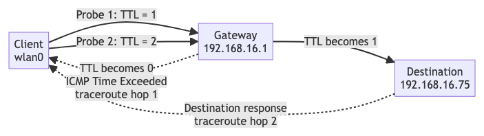
If the destination were reached directly at Layer 2, a switch could forward its Ethernet frame without touching the IP TTL. Traceroute would normally show the destination as hop 1.
The additional hop is thus not produced by the ARP reply itself. It appears because the device that supplied the MAC also performs Layer 3 forwarding:
Proxy ARP selects the gateway MAC
              +
Gateway routes and decrements TTL
              =
Gateway appears in traceroute
Part II — From one local hop to the whole Internet
The same division of responsibility explains how two hosts communicate across the Internet. A client normally does not know the remote server’s MAC address. It does not need to.
A MAC address has meaning only on the current Layer 2 link. Ethernet and Wi-Fi do not carry one frame unchanged across the Internet. Every router removes the incoming link-layer header, processes the enclosed IP packet, and creates new link-layer framing for the next link.
The following fictional example uses IPv4 ranges reserved for documentation:
| Role | Address |
|---|---|
| Private client | 192.168.1.10:51514 |
| Client’s default gateway | 192.168.1.1 |
| Gateway’s public NAT mapping | 198.51.100.10:62000 |
| Public HTTPS server | 203.0.113.20:443 |
The values after : are TCP ports. A destination IP identifies a Layer 3 routing endpoint, while the destination port selects a transport endpoint and ultimately an application socket.
What identifies the final target?
There is no single universal identifier at every layer. Communication succeeds because each mechanism answers a smaller question:
| Mechanism | Question it answers |
|---|---|
| DNS | Which public IP address currently represents this service name? |
| Destination IP | Which host or network interface should receive the packet? |
| TCP/UDP destination port | Which service on that host should receive the data? |
| Subnet mask and local routes | Is the destination on-link, or must a gateway be used? |
| Router forwarding table | Which next hop moves this destination prefix closer to its network? |
| ARP | What MAC address can receive the packet on this local IPv4 link? |
| Switch MAC table | Through which Layer 2 port should this frame leave? |
| NAT state | Which private connection corresponds to this public IP and port? |
| TTL | How many more Layer 3 forwarding hops may the packet cross? |
An application may begin with a name such as www.example.test. DNS resolves that name to an IP such as 203.0.113.20. The application selects port 443 for HTTPS. Together, the destination IP and destination port identify the remote network endpoint for this connection.
The remote MAC is not part of that identity. It may be thousands of kilometers away and separated from the client by many different Layer 2 technologies. The client only needs the MAC of the next hop on its own link.
Outbound: private client to public server
1. The client creates the transport and IP headers
The operating system chooses an ephemeral source port, here 51514, and creates a TCP segment:
TCP source port:      51514
TCP destination port: 443
It then places that segment in an IP packet:
IP source:      192.168.1.10
IP destination: 203.0.113.20
2. The subnet mask selects direct delivery or a gateway
The client compares 203.0.113.20 against its connected subnet. The public address is not inside the client’s private network, so the routing table selects the default route:
default via 192.168.1.1
This decision is different from the Proxy ARP case:
- in the case study, the
/20route classified the peer as on-link, so the client issued ARP for the peer IP; - for an Internet destination, the route classifies it as off-link, so the client issues ARP for the gateway IP.
3. ARP finds only the first-hop MAC
The client asks:
Who has 192.168.1.1?
Suppose the gateway replies with fictional MAC 02:00:00:00:01:01. The first frame is then:
Ethernet source:      client's MAC
Ethernet destination: gateway's LAN MAC
IP source:            192.168.1.10
IP destination:       203.0.113.20
The Layer 2 destination and Layer 3 destination intentionally name different devices. The frame is for the next hop; the enclosed packet is for the final server.
4. A switch delivers the local frame
A Layer 2 switch learns source MAC addresses and associates them with switch ports. It forwards the frame toward the port where it learned the gateway’s MAC.
This is the scope of Layer 2 forwarding: it delivers frames inside the current Layer 2 network. It does not choose an Internet route and it does not inspect or decrement IP TTL.
5. The home gateway applies NAT
Private address 192.168.1.10 is not globally routed on the public Internet. The home gateway therefore creates a NAT/PAT mapping:
inside:  192.168.1.10:51514
outside: 198.51.100.10:62000
remote:  203.0.113.20:443
The outbound packet becomes:
IP source:            198.51.100.10
TCP source port:      62000
IP destination:       203.0.113.20
TCP destination port: 443
NAT changes the source IP and often the source port at this one boundary. Ordinary routers after it do not keep changing those values. They normally preserve both endpoint IP addresses and transport ports while decrementing TTL.
6. Every router makes one next-hop decision
An Internet router does not need the sender’s complete path to the server. It reads the destination IP, performs a longest-prefix match in its forwarding information base, and obtains:
- an outgoing interface;
- a directly reachable next hop, or a directly connected destination.
The router then resolves or retrieves the next hop’s link-layer address, creates new link-layer framing, and transmits the packet.
This repeats independently at every router:
destination IP → longest matching route → next hop → local link delivery
Routing protocols such as BGP and internal gateway protocols distribute reachability information from which routers build their tables. The data packet does not carry a list of all routers it must visit.
7. The final link reaches the server
Eventually a router has a connected route for the server-side network. On an Ethernet-like IPv4 link, it uses ARP to learn the server’s MAC and creates the final frame:
Ethernet source:      final router's MAC
Ethernet destination: server's MAC
IP source:            198.51.100.10
IP destination:       203.0.113.20
Only this final router needs the server’s MAC. The original client never learns it.
Complete outbound and return flow
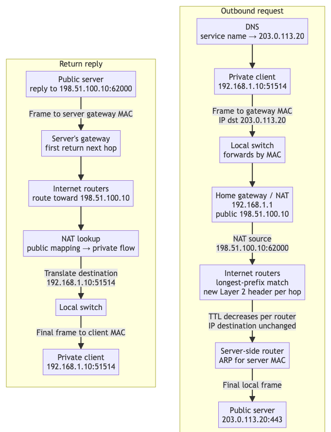
The diagram separates three different kinds of state:
- Layer 2 state is local to each link and changes at every routed hop.
- Layer 3 destination state guides the packet across routers toward the public server.
- NAT connection state associates the public translated flow with the private client flow.
Return: public server to private client
The server receives a connection from:
198.51.100.10:62000
It does not see the client’s private 192.168.1.10 address. To reply, the server creates:
IP source:            203.0.113.20
TCP source port:      443
IP destination:       198.51.100.10
TCP destination port: 62000
Because 198.51.100.10 is outside the server’s local subnet, the server sends the frame to its own default gateway’s MAC—not to the client’s MAC and not necessarily to the MAC of the router that delivered the request.
Routers forward the reply toward 198.51.100.10. The return path can differ from the outbound path; IP routing does not require symmetry.
When the reply reaches the NAT gateway, the gateway looks up its state:
198.51.100.10:62000 → 192.168.1.10:51514
It rewrites the destination IP and port, consults its route for 192.168.1.10, obtains the client’s local MAC through ARP or its neighbor cache, and transmits the final local frame.
This NAT state is why a reply can reach a client whose private address is not routed on the Internet. Without an existing mapping, port-forwarding rule, or similar policy, an unsolicited inbound packet generally cannot identify which private host should receive it.
What changes at each stage?
For the outbound direction:
| Field | Client LAN | Public Internet after NAT | Final server link |
|---|---|---|---|
| Source IP and port | 192.168.1.10:51514 |
198.51.100.10:62000 |
198.51.100.10:62000 |
| Destination IP and port | 203.0.113.20:443 |
203.0.113.20:443 |
203.0.113.20:443 |
| Source MAC | client | current router/interface | final router |
| Destination MAC | home gateway | next router on that link | server |
| TTL | initial value | decreases once per router | lower than initial value |
The key correction is:
MAC addresses change at routed link boundaries. In ordinary outbound communication through source NAT, only the initiator’s private source IP and possibly its source port are translated; the responder IP and port selected by the initiator remain unchanged. Return traffic receives the inverse translation so it reaches the private initiator.
From the initiator’s perspective, it communicates directly with the destination IP and port it selected. A gateway may later apply destination NAT, load balancing, or proxying to reach a different backend, but reverse translation preserves the original endpoint as the initiator’s logical peer. Ordinary routers perform neither translation: they preserve the IP endpoints while replacing the Layer 2 framing and decrementing TTL.
IPv6 uses the same next-hop principle, although Neighbor Discovery replaces ARP and ordinary IPv6 Internet access generally does not require address translation.
Part III — Symmetric protocols, asymmetric initiation
IP does not define client and server roles. Its packet format is symmetric: every packet has a source and a destination, and either reachable host can theoretically send to the other.
UDP is similarly peer-neutral. It carries independent datagrams in either direction. TCP does distinguish an active opener, which sends the first SYN, from a passive opener, which listens for it, but the established TCP connection is full-duplex: either side can send application data.
The practical asymmetry begins with the application:
The initiator must first obtain a reachable address for the responder.
It might obtain that address from DNS, configuration, service discovery, or a rendezvous service. The responder does not need to know the initiator in advance; it listens on a known address and port and learns the initiator’s observed source endpoint from the first packet.
The destination must be unambiguous and reachable in the initiator’s routing context. For ordinary Internet communication, this normally means a globally routable public service IP. From the initiator’s perspective, that IP and port are the final logical responder:
initiator ↔ selected destination IP:port
The selected address does not have to identify one physical server. It may represent an anycast service, CDN edge, load balancer, reverse proxy, or public address translated to a private backend. Those systems preserve the selected endpoint as the initiator’s logical peer, so their internal backend selection is normally invisible to it.
Initiator and responder are roles, not IP properties
“Client” and “server” often align with initiation, but they are application roles rather than properties imposed by IP:
| Network behavior | Precise term |
|---|---|
| Sends the first packet | Initiator |
| Waits for the first packet | Responder |
Sends the first TCP SYN |
Active opener |
Listens for a TCP SYN |
Passive opener |
| Requests an application service | Client |
| Provides an application service | Server |
The key question under NAT and stateful firewalls is:
Which side sends first and creates the translation and filtering state required for the reverse traffic?
That first packet creates the practical asymmetry. It does not make IP or UDP intrinsically client/server protocols.
IP does not listen on ports
“Listening on a port” is not an IP-layer operation. An IP header contains source and destination IP addresses plus a protocol number, but it contains no TCP or UDP ports:
IP destination + protocol number
               │
               ├── protocol 6  → TCP
               ├── protocol 17 → UDP
               └── protocol 1  → ICMP
After link-layer filtering, IP validation, routing, and firewall processing, the kernel’s IP layer decides whether an accepted packet is for the local host and which upper-layer protocol should receive it. Only then does TCP or UDP inspect its own header and perform a socket lookup using IP addresses and ports.
TCP supports the passive-open mechanism commonly called listening:
bind(local IP, port) → listen() → accept()
The TCP subsystem first looks for an established connection matching the source/destination IP-and-port tuple. For a new SYN, it may instead find a listening socket for the local address and port. If no socket matches, the kernel normally rejects the attempt with TCP RST.
UDP has ports but no TCP-style listen or accept operation:
bind(local IP, port) → recvfrom()
The UDP subsystem delivers a datagram to a matching bound socket. If none exists, the host may return ICMP Port Unreachable.
The precise separation is:
IP delivers an accepted packet to the appropriate transport protocol. TCP or UDP uses port numbers to select a socket. The socket layer connects that transport endpoint to an application; only TCP has the specific listen/accept mechanism.
Where state actually lives
“Stateful” and “stateless” only make sense after naming the layer or component:
| Component | State model |
|---|---|
| IP | Stateless packet delivery; no connection handshake or connection table |
| UDP | Connectionless transport; no built-in session establishment, acknowledgement, or teardown |
| TCP | Stateful transport; endpoints maintain sequence numbers, windows, retransmission state, and a connection state machine |
| NAT gateway | Stateful translation; maintains mappings between private and public flow endpoints |
| Stateful firewall | Tracks flows to decide which return or inbound packets are allowed |
| Application | May maintain its own login, request, messaging, media, or reliability session over TCP or UDP |
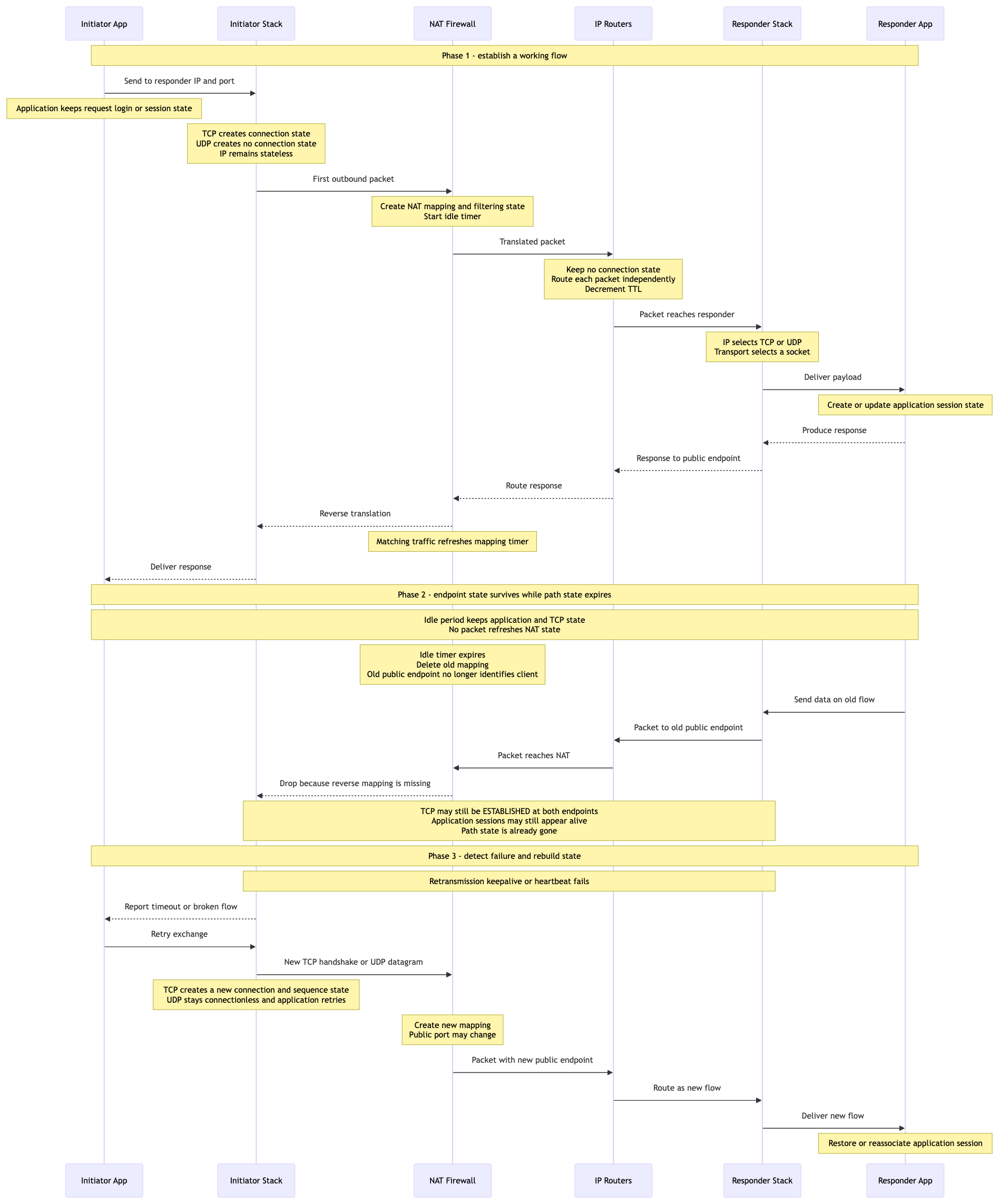
The sequence separates three phases and identifies the state affected at every step:
- The initiator application creates request or session state and asks its transport stack to send.
- TCP creates connection state; UDP does not. In both cases, IP treats each packet independently.
- The first outbound packet creates NAT translation and firewall-filtering state with an idle timer.
- Ordinary routers keep no connection state; each performs an independent destination-route lookup.
- The responder’s IP layer selects TCP or UDP, the transport layer selects a socket, and the application creates or updates its own session state.
- A matching reply uses reverse NAT translation and refreshes the middlebox timer.
- During an idle period, endpoint TCP and application state may remain alive while NAT/firewall state expires independently.
- A later packet for the old public endpoint is dropped because the reverse mapping no longer exists, even though both TCP endpoints may still report
ESTABLISHED. - Retransmission failure, TCP keepalive, or an application heartbeat eventually exposes the broken path.
- TCP performs a new handshake, while UDP sends a new datagram and lets the application retry. NAT creates a new mapping whose public port may differ, and the application restores or re-associates its session.
UDP being connectionless does not make the entire path or application stateless. QUIC, voice/video calls, games, and many other stateful applications run over UDP. Meanwhile, a NAT gateway usually creates temporary UDP mapping state when the first outbound datagram crosses it:
UDP
192.168.1.10:51514
        ↕ NAT mapping
198.51.100.10:62000
While that mapping exists, a response sent to 198.51.100.10:62000 can be translated back to the private client. If it expires, a late response normally reaches the gateway but cannot be associated with a private endpoint, so it is dropped. A new outbound datagram can create a new mapping—possibly with a different public port—but the application must retry or restore any higher-level exchange.
UDP mapping timeouts vary. RFC 4787 says a general UDP mapping must not expire in less than two minutes of inactivity, with limited exceptions, and recommends a default of at least five minutes. UDP applications with longer idle periods often send keepalives.
TCP endpoints maintain connection state, but an idle TCP connection does not necessarily transmit packets. Data, acknowledgements, optional TCP keepalive probes, or application heartbeats refresh intervening NAT and firewall state. RFC 5382 requires a compliant NAT’s established TCP idle timeout to be at least two hours and four minutes, although real network equipment and firewall policy can vary. RFC 1122 specifies that TCP keepalive is optional, disabled by default, configurable per connection, and traditionally defaults to an idle interval of at least two hours.
If a TCP mapping disappears while both endpoints still consider the connection established, their state becomes inconsistent:
client TCP state: ESTABLISHED
server TCP state: ESTABLISHED
NAT flow state:   missing
The client and server cannot resume that old connection merely by creating another NAT mapping. The server identifies the TCP connection by its protocol and source/destination IP-and-port tuple; a new mapping may produce a different public endpoint. Packets for the old tuple are dropped or no longer translated correctly. One endpoint eventually detects retransmission failure, a keepalive failure, an application heartbeat timeout, or an explicit close, then creates a new TCP connection with a new handshake and restores any application session.
A recreated mapping may expose the initiator through a new public port:
old flow:
198.51.100.10:62000 ↔ 203.0.113.20:443

new flow:
198.51.100.10:62001 ↔ 203.0.113.20:443
The responder’s service endpoint, 203.0.113.20:443, normally remains unchanged. What changes is the translated endpoint from which the responder observes the initiator. Replies for the new flow must target 198.51.100.10:62001; traffic sent to the expired 62000 mapping can no longer reach the private client. A NAT may reuse the old public port, but applications cannot depend on that behavior.
For TCP, the new endpoint belongs to a new connection with a new handshake, sequence-number space, and connection state—even if the NAT happens to reuse the same public port. For UDP, a new outbound datagram can create the replacement mapping without a transport handshake, but any higher-level session must recognize the new observed endpoint or re-establish its application identity.
Multiple NATs form one translation chain
A real path may contain a home NAT, an ISP carrier-grade NAT, and additional stateful gateways. Each one contributes a mapping:
private client
192.168.1.10:51514
        │
        ▼ home NAT
100.64.1.20:61000
        │
        ▼ carrier-grade NAT
198.51.100.10:62000
        │
        ▼
server
203.0.113.20:443
The server sees only the outermost public endpoint, but the return path depends on the complete reverse chain:
198.51.100.10:62000
        ↓ carrier-grade NAT mapping
100.64.1.20:61000
        ↓ home NAT mapping
192.168.1.10:51514
Every required mapping must remain valid. If any dynamic mapping expires, the old reverse path is interrupted at that device. The NAT normally gives neither endpoint an immediate notification; the failure appears only when data, retransmissions, keepalives, or application heartbeats stop succeeding. A keepalive that crosses the complete path can refresh the mappings it traverses, so the effective idle lifetime is controlled by the shortest relevant NAT or firewall timeout and its refresh policy.
New outbound traffic may create a new chain, but “a new path exists” does not mean “the old transport flow survived.” A flow is normally classified by its 5-tuple:
(protocol, source IP, source port, destination IP, destination port)
For TCP, changing any element identifies a different connection. Suppose the established server-side tuple is:
TCP
198.51.100.10:62000 ↔ 203.0.113.20:443
After remapping, an old TCP data segment may reach the server as:
TCP
198.51.100.10:63000 → 203.0.113.20:443
The server has no established connection for that tuple. A non-SYN segment is normally rejected with RST or dropped; it cannot be attached to the connection that used port 62000. The application must abandon the old flow and initiate a new TCP handshake. If every NAT happened to reconstruct exactly the same externally visible tuple and allowed midstream packets, the old flow might continue, but applications cannot rely on that exceptional outcome.
For UDP, the same 5-tuple identifies a network flow but not a transport connection. A server socket bound to 203.0.113.20:443 can receive a new datagram from 198.51.100.10:63000 and reply to that newly observed endpoint. The application decides whether it is:
- a new independent request;
- the same authenticated session, identified by an application token;
- a peer that must re-register because its source tuple changed;
- a transport such as QUIC that uses a connection ID to survive address or port rebinding.
The precise rule is:
Losing any required NAT mapping breaks the old response path. Rebuilt mappings may create a new response path. TCP normally requires a new handshake when the public 5-tuple changes; UDP can use the new path immediately, but application-level state determines whether the logical session continues.
This explains why a server-side connection can become unusable even while the client device and process remain alive. “The client is alive” does not prove that:
- its old network path still exists;
- its NAT and firewall mappings still exist;
- it retained the same public IP and port;
- its operating system still holds the same socket;
- the application remained active while the device slept or changed networks.
The server may temporarily retain a stale ESTABLISHED socket because TCP has not yet received evidence of failure. Conversely, an application or server may close an idle connection by policy even when the underlying NAT mapping remains valid. Keepalives and heartbeats both refresh state and help discover these half-open or unreachable flows sooner.
What NAT changes about that relationship
Without NAT or firewall restrictions, either globally reachable host can initiate traffic to the other. With ordinary source NAT, the private host normally must send first:
actual initiator:   192.168.1.10:51514
observed initiator: 198.51.100.10:62000
responder:          203.0.113.20:443
The initiator knows the responder’s reachable destination, 203.0.113.20:443. The responder learns and replies to 198.51.100.10:62000. It does not learn the private 192.168.1.10:51514 address from the IP and TCP headers.
The responder therefore does know an address for the initiator, but it is the translated public endpoint, not necessarily the initiator’s actual interface address. That public endpoint is usable while the NAT mapping and firewall state permit the flow. It does not necessarily allow the responder to create an unrelated inbound flow later.
Unlike the responder’s reachable logical destination, the initiator’s original source address need not be globally unique:
Home A client: 192.168.1.10:51514
Home B client: 192.168.1.10:51514
The identical private endpoints are valid because they exist in different routing domains. NAT gives each flow a usable public mapping. Even that public IP can be shared by many clients, distinguished by ports, protocol, and connection state:
198.51.100.10:62000 → private client A
198.51.100.10:62001 → private client B
This is the practical initiation asymmetry:
The initiator must know a reachable logical destination, but its own address need not be globally unique or independently reachable. The responder returns traffic to the translated source endpoint created for that flow.
This applies to both TCP and UDP. In this context, “initiator” means the side that sends the first packet and creates the necessary network state—not necessarily a TCP client.
Two private hosts in different networks
Suppose two users are behind unrelated home routers:
User A: 192.168.1.10 behind NAT A
User B: 192.168.1.10 behind NAT B
Their identical private addresses are not a conflict because the addresses belong to different routing domains. Neither private address is globally reachable, so A cannot simply send an Internet packet to B’s 192.168.1.10.
A messaging service commonly solves this with two outbound connections:
User A ──outbound connection──► public service
User B ──outbound connection──► public service
When A sends a message to B:
- A sends it through A’s established connection to the public service.
- The service identifies B by an application identity, not by B’s private IP.
- The service delivers it through B’s separate established connection.
- B’s NAT mapping directs the returning packets to B’s private endpoint.
In this design, the publicly reachable service is a relay and the two clients never need to learn each other’s IP addresses.
A relay is common, but it is not always required for the entire data path. Peer-to-peer systems may use a public rendezvous service to discover the peers’ translated public IP-and-port mappings, then try STUN, ICE, and UDP hole punching to establish a direct flow:
NAT A public mapping ← direct packets → NAT B public mapping
If their NAT or firewall behavior prevents a direct flow, a public relay such as TURN carries the traffic. The accurate rule is therefore:
Two private hosts in different networks usually need publicly reachable infrastructure for discovery and coordination; they often use it as a relay, but compatible NAT traversal can sometimes create a direct public-mapping-to-public-mapping path.
The final source of practical asymmetry
NAT is the main mechanism that turns private/public addressing into strong initiation asymmetry, but it is not the only source. Three related asymmetries build on one another:
- Application roles: the responder publishes or waits on a known endpoint; the initiator discovers that endpoint and sends first. The responder learns the initiator’s observed source only after receiving the first packet.
- Address scope: a public service endpoint is reachable through public routing, while a private address such as
192.168.1.10is meaningful only inside its own routing domain and can be reused elsewhere. - NAT and firewall state: the private side normally sends first to create the mapping and filtering state through which the responder can return traffic. Without existing state or an explicit inbound rule, the public side cannot start an unrelated flow directly to that private host.
The resulting behavior is:
| Initiator behind NAT | Public responder |
|---|---|
| Knows a reachable responder endpoint before sending | Learns the initiator’s translated endpoint from the first packet |
| Creates outbound NAT and firewall state | Replies through that existing state |
| May use a private, non-globally-unique source address | Exposes a publicly reachable logical service endpoint |
| Usually cannot receive a new unsolicited public flow | Can wait for new flows on its published endpoint |
The protocols themselves remain symmetric where appropriate: IP packets always contain source and destination addresses, UDP can carry datagrams in either direction, and an established TCP connection is full-duplex. The practical asymmetry comes from the combination:
application discovery and roles
               +
private versus public routing scope
               +
NAT and stateful-firewall flow state
               =
practical initiator/responder asymmetry
In the ordinary outbound case, the initiator must know a reachable logical responder endpoint, but its own private address need not be globally unique or directly reachable. NAT supplies a temporary translated endpoint for the flow, and the responder returns traffic through that state.
Final summary: the communication path is also state
Before useful TCP/IP or UDP/IP communication can occur, there must be a usable network path between the endpoints. This does not mean that IP reserves one end-to-end circuit. Instead, the operational path is assembled from two kinds of behavior:
- Routing reachability: each host or router independently selects the next hop for the destination prefix.
- Middlebox state: every NAT or stateful firewall on the path maintains the mapping and filtering information needed to carry the flow and its replies.
The initiator must know a reachable responder IP and port and send the first packet. That packet follows routing decisions hop by hop and creates any required dynamic NAT and firewall state:
initiator sends first packet
        ↓
host selects first next hop
        ↓
routers select successive next hops
        ↓
NATs and firewalls create flow state
        ↓
responder receives the packet
        ↓
reply follows the available reverse mappings
The resulting path is not represented by one global table. It is the composition of all routing decisions, Layer 2 next-hop deliveries, and stateful mappings along the way. The upper-layer communication channel depends on the entire composition remaining usable.
This creates a crucial failure mode:
Two endpoint applications and their sockets may still be alive while the network path state between them has already disappeared.
If any required NAT or firewall mapping expires, the old reverse path is broken. A responder may continue sending to the old public IP and port, but the expired mapping can no longer identify the private endpoint. Neither endpoint necessarily receives an immediate notification; the failure is discovered later through missing responses, retransmission timeout, TCP keepalive, or an application heartbeat.
The initiator must then create a new operational path:
- TCP: abandon the old connection and perform a new handshake. A changed public 5-tuple represents a different TCP connection.
- UDP: send a new outbound datagram to create fresh mappings. UDP itself has no connection to restore, so the application decides whether the new source endpoint continues the old logical session.
The application layer must therefore assume that network-path state can fail independently of endpoint state. Robust applications need appropriate combinations of:
- timeout and failure detection;
- retry and reconnection;
- TCP keepalive or application heartbeat where justified;
- session tokens or connection IDs that survive transport rebinding;
- idempotency or duplicate handling for retried operations;
- re-authentication and session restoration after a new path is created.
The central lesson is:
The side that sends first establishes the usable dynamic path through any NATs and stateful firewalls. Upper-layer communication can continue only while that path remains valid. When intermediate state expires, the endpoints may remain healthy, but the old communication channel is broken and must be recreated or rebound.